Fire Fighting Robot
MENG 483 - MECHATRONICSCOURSE PROJECT
TECHNICAL REPORT
MAY 10, 2011
ABSTRACT
The objective of this project was to deploy a robot used to detect, navigate towards, and extinguish a small flame. The design consisted of a LEGO Mindstorms NXT robotic interface augmented with a UV sensor used to detect a flame and a small fan attached to a motor to extinguish the flame. The system proved to navigate towards and extinguish a small flame successfully.
1. INTRODUCTION
The objective of this project was to deploy a robot that was capable to detect, navigate towards, and extinguish a small flame. Future, applications of this project are aimed towards an automated fire-extinguishing system installed in a home that introduces a significant degree of safety beyond a typical smoke-detector. A robot would be able to detect an extreme heat source in a room and navigate around furniture or anything else in its path making its way to the flame. To the group's knowledge, there has been no attempt to commercialize a larger-scale system.
Previous work by others includes similar robotic projects to extinguish small flames capable of following a traveling flame as well as being able to locate a candle up to five meters away in a maze. Those previous robots needed to physically run into the candle to start the fan and continued to run well after the candle was put out. The robots also had a rear mounted fan; and as a result, they needed to turn around to extinguish the flame. The group has planned to mount the fan on the front of the robot, in order to eliminate the need for rotation-since rotation may cause disturbance to the objects around the flame. Also, once in close proximity the robot would activate the mounted fan instead of having to come in contact with the flame.
2. SYSTEM DESIGN
The robot is composed of a LEGO Mindstorms NXT robotic interface. The interface uses two wheels, each mechanically actuated, and a third, free-rotating wheel for balance. On top of the mechanical head is a UVTRON sensor used to detect the flame. In front of the robot is an extinguishing unit; in this case a RE-260RA DC Motor with a fan blade attached to it. The robot is communicated with via Bluetooth through a laptop that runs the program.
As previously mentioned, the system is designed detect, navigate towards, and extinguish a small flame. This task is accomplished through a C++ code (see appendix C). Once the code is executed, it gives instructions to the robot and its attached sensors and actuators. The Bluetooth enables the system to be controlled wirelessly allowing for ease of motion. UVTRON sensor takes readings from surroundings as the robot is rotated; it detects changes in n ultraviolet radiation. The program then instructs the Mindstorms NXT robotic interface to move forward activating the two driving wheels. After every two inches traveled the UVTRON takes another reading of the surroundings and continues to until reaching the flame. Once it reaches the flame the fan is switched on and runs until the UVTRON does not detect the flame anymore.
2.1 MECHANICAL DESIGN
The robot is a LEGO Mindstorms NXT robotic interface. The interface is attached to three wheels, two wheels that are individually mechanically actuated. The robot also consists of a third wheel used to balance and help navigate the robot. On the top of the interface, an attachment was modeled in SolidWorks and printed in New Mexico Tech's rapid prototyping machine (3D printer) to hold the UVTRON sensor. The design also consists of a DC motor which will power a fan used to extinguish the flame. The fan will be custom designed and made using the 3D printer. In order for the UVTRON to function properly, a shield was constructed in order to eliminate ambient light interference. Construction consists of a covering that encompasses the entire sensor but with a small slit cut in the font. This way the sensor can only detect what is directly in front of the robot and determine which is the highest UV source as the robot rotates.

Figure 1: UV TRON Circuit connected to Brick via Printed Mount
2.2 ELECTRICAL DESIGN
LEGO Mindstorms NXT
The robot is power by the LEGO Mindstorms NXT, a programmable robotics kit released by LEGO in late July 2006. It replaces the first-generation LEGO Mindstorms kit, which was called the Robotics Invention System. This particular version is the Retail Version #8527. The main component in the kit is a brick-shaped computer called the NXT Intelligent Brick. It can take input from up to four sensors and control up to three motors, via RJ12 cables, very similar to but incompatible with RJ11 phone cords. The brick has a 100x64 pixel monochrome LCD display and four buttons that can be used to navigate a user interface using hierarchical menus. It also has a speaker and can play sound files at sampling rates up to 8 kHz. Power is supplied by 6 AA (1.5 V each) batteries or by a Li-Ion rechargeable battery.

Figure 2: NXT Intelligent Brick
This particular robot design uses LEGO NXT 2 motors for the wheels; these are continuous servo motors that have built-in reduction gear assemblies with internal optical rotary encoders that sense their rotations within one degree of accuracy. Also included in this design is a ultrasonic sensor for detecting distance and a light sensor for detecting light/color variations on the ground.
UV TRON Sensor
The Hamamatsu flame sensor UV TRON R2868 sensor package features a UV TRON bulb. The detector makes use of the photoelectric effect and the gas multiplication effect. This works by UV light hitting a filament in a bulb attached to the board; as this occurs electrons are discharged into a thin plate, which is then converted by the on board electronics to a useable. It has a spectral sensitivity of 185 to 260nm. The UV TRON bulb is attached to the UV TRON Driving Circuit C3704. The circuit allows the flame sensor to operate a low input voltage between 6 to 30V value.

Figure 3: UV TRON Driving Circuit and Sensor Bulb
The output from the board is modulated as a low pulse signal (a voltage drops from high to low at a frequency depending on the strength of the flame). When a flame was directly in front of the UVTRON this was at a frequency of 10 Hz; therefore, as the flame was moved away or covered, this frequency would drop to zero.
Adapter Board
Since the NXT uses a two data-power wire system (using the black and white wires), an adapter had to be created to separate the data wire from the power wires. This is done by the use of a 1kΩ resistor, a 1N4148 diode, an operational amplifier, and a 22uF 16V capacitor.

Figure 4: Adapter Circuit
The above image uses a LM324 Quad op-amp; however, this op-amp is quite large (14-pin DIP) and so it was substituted with a LM741CN (8-pin DIP), this substitution is also extremely easy to find and costs less.
Once this circuit was successfully adapted into a breadboard, a permanent circuit layout was design and then was created using a perfboard as see below.

Figure 5: Physical Adapter
In order to make this layout as compact as possible, one of the unused legs of the socket was cut off. This board was then modified to work with a socket connector for both the UVTRON, and the NXT cable; the result can be seen below.

Figure 6: Modified Adapter Board
Below are some pictures that show how the Adapter board is attached to the UV TRON and NXT cable.

Figure 7: Adapter Board Attached
During the programming of the UVTRON using the adapter plate, when a flame is detected, the NXT registers a zero; and when no flame is present, the NXT resisters a hundred. Therefore this sensor can be defined in class as a Boolean device.
Fan Motor
A 4.5V (max) RE-260RA DC Motor was used for the fan motor. The body mount was constructed using the 3D printer, and attachments were made to allow it to be LEGO compatible. This motor was attached to an NXT cable through the black and white power cables, since this motor can be rotated in either direction, it did not matter which was the wires were connected to the motor (rotation can also be set using software). Although the NXT can supply up to 9V, it is also able to adjust how much power is supplied to its motors, as such the program has limited this max power to 4.5V.


Figure 8: DC Motor with Cover
2.3 SOFTWARE DESIGN
The team used basic C++ programming in its coding (see appendix C for full code). The basic premises for the code were to first define the movement for the robot, and then define what it was to do with the movement. The team programmed it to rotate in increments of around thirty degrees, and detect the highest intensity of UV light given off by the flame. From there, the robot would move towards that source a finite distance, and then repeat the detection. It would repeat this process until it came to a defined intensity in the UV light, face it, and actuate its fan to extinguish the flame.
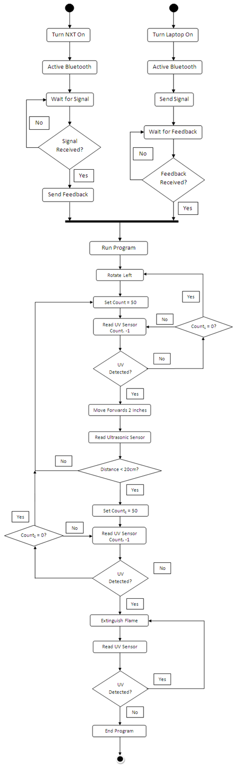
Figure 9: Logic Flow Diagram for Flame Navigation Program
Motors B & C are used for the robots wheels, Motor A is used for the fan. The speed of all the motors are set to ten (out of 100) to allow for smooth movement and accuracy. Sensor one is the UVTRON for detecting the flame and Sensor three is the Ultrasonic sensor for detecting distance from the candle.
The Bluetooth Remote Programming Software "NXTurary" (Previously known as "InterNXT") is a custom designed software that allows the NXT to be used as a remote data-logging device. While most NXT software use the onboard processing and storage memory to store and run programs, this software allows the computer to be used for processing and storage and remotely control the NXT (using Bluetooth) either through user input or programming lines; as the computer runs through the program it informs the NXT of what it needs to do such as read sensors or run actuators. By using this type of software, the limitations of the NXT are removed and therefore is only bound by the limitations of the user's computer. This software is developed by Paul NeoStormer and is written in C++ using the Dev-C++ compiler by Bloodshed Software.
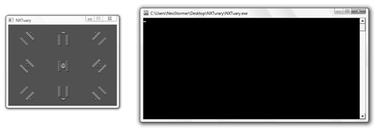
Figure 10: User Interface for the Robot Control Screen in the NXT Software

Figure 11: NXT Software and Programming Environment
2.4 SYSTEM ASSEMBLY
Assembly Experience: Some mounting parts that were needed -including the fan blade, motor mount, and circuit mount- were modeled in SolidWorks and printed using the 3D Printer. The circuitry for the UV sensor had required various iterations on a prototyping board before being built in a permanent circuit board. As far as the software, the labs helped with the encoding of the detection, especially the light intensity sensor lab eight.
Success and Difficulties: Successes and difficulties varied accordingly throughout this project. Manually navigating the robot, having the UV sensor emit a high frequency sound when it detected fire, and connecting the circuit to the robot proved successful; however, when the components as a whole came together, some difficulties arose. It was difficult shielding the UV sensor from detecting non-flame UV light, and being able to filter the other frequencies of UV light. Since the sensor was unable to detect the flame as accurate and sensitive as we had liked, it made it difficult for the robot to detect the flame at farther distances. This didn't properly allow the robot to navigate towards the flame source. The team also had issues with the fan not being able to be printed, due to either errors in printing or the printer being occupied.
What Worked and Didn't Work: As previously mentioned, the robot itself, circuitry and equipment worked fine, however the sensor didn't work as accurately over distances further than five meters as we had hoped for. Also, the fan blade wasn't able to print before presenting the project.
Solutions and Recommendations: The team managed to fix the sensor issue by properly shielding it from outside sources of UV light. This allowed for the robot to more accurately detect the direction of the flame and therefore navigate it more efficiently. As a result, the team has found that properly shielding the sensor towards a discrete direction, increased the overall accuracy and efficiency of the robots ability to detect the flame, and navigate towards it. The team also encoded the robot to stop in front of the flame approximately twenty centimeters away, using the ultrasonic sensors.
3. SYSTEM TESTING
While this project was coming together, various subsystems were tested individually, then assembled together and re-tested. First, the NXT robotic interface was assembled, and coded in order to be manually controlled via a Bluetooth connection in a laptop. From there, a circuit was prototyped for the UV sensor to test the detection of a flame. It was encoded to sound a high-frequency sound when a flame was sensed. Once this proof-of-concept was working properly, an adapter circuit was made into a permanent circuit, where it was then mounted and tested again. The DC motor and fan was then mounted to the robot, and software coding began.
Testing of the robot itself consisted of first, lighting a candle in front of the robot, then having the robot turn in increments of around thirty degrees until it detects the flame. Once the robot detects the flame, it gives off a sound. The group then tested the robots ability to navigate towards the flame. Finally, the group had to test the extinguishing mechanism, and the UV ultrasonic sensor to ensure the robot doesn't run into the flame.
4. MATERIAL COST AND PARTS LIST
A majority of the components of this project were purchased prior to starting. None of the components were purchased with department funds.
| Component | Cost | Previous or Current Purchase |
|---|---|---|
| LEGO Mindstorms Kit: | $250.00 | Previous |
| Hamamatsu UV TRON Sensor | $40.00 | Previous |
| Hamamatsu UV TRON Circuit board | $90.00 | Previous |
| RE-260RA DC Motor | $6.00 | Previous |
| Adaptor plate | $0.50 | Current |
| LM741CN Op-amp | $1.00 | Current |
| 1N4148 Silicon Switching Diodes (50 Pack) | $3.00 | Current |
| Resistor 1KΩ (5 Pack) | $1.00 | Current |
| Total | $391.50 |
5. CONCLUSION
The major achievements of this project were mainly the completion of the circuitry and hardware, properly attaching it, completion of the coding, and testing the robot. However, after tedious work and troubleshooting, the team was able to successfully assemble a robot that was able to detect, navigate towards, and activate a DC motor in the direction of the flame. This marked the completion of our goal for this project.
6. REFERENCES
"C3704 Hanamasu ." Data sheets. N.p., n.d. Web. 7 May 2011.
<http://www.datasheetcatalog.org/datasheet/hamamatsu/C3704.pdf>.
"LEGO NXT." Lego Data Sheets. N.p., n.d. Web. 8 May 2011. PDF.
"LM741 Op-Amp." Data sheets. N.p., n.d. Web. 7 May 2011. PDF.
"RadioShack - mobile phones, MP3 players, laptops, and more." RadioShack - mobile phones, MP3 players, laptops, and more. N.p., n.d. Web. 10 May 2011.
"UVTRON R2868." Acroname Robotics. N.p., n.d. Web. 10 May 2011.
<http://www.acroname.com/robotics/parts/R2868.pdf>.